SO YOU WANT TO BUILD A WIRELESS USING GERMANIUM CRYSTAL TRIODES.
There is a far off twilight era that has always fascinated me. It is that obscure, sparsely documented, misty period between the announcement of the world's first practical crystal amplifying device, in 1948, and the dawn of the commercially available Transistor Radio in Britain. If I had been an average radio enthusiast or constructor at that time then I would have been coming to terms with the new miniature all glass valves, learning about the possibility of new TV channels or reading about how to incorporate strange FM circuitry into the Domestic Wireless set. However, if I had also followed the accounts from America, since its introduction, of this exotic device called a Germanium Triode and had been further tantalized by snippets in the radio press referring to its experimental production by British companies and also harboured a desire to build a circuit using it, what would have been available to me in terms of circuits or guidance?HISTORY
First let us put down a few mile posts so we can see exactly where we are in the scheme of things. What had been officially announced in June 1948 by Bell Telephone Laboratories was a Point Contact Transistor. Journals subsequently referred to it quaintly as a Germanium Triode or a Crystal Valve. It had many drawbacks and wayward characteristics but it worked and it paved the way for other devices. Amongst early contenders in the field in the U.K. were British Thompson Houston and G.E.C. both of which appear to have produced point contact transistors in 1948 and there is new evidence from France to challenge the Bell claim that they were the sole inventors (see postscript).In 1951 Shockley at Bell announced a working junction transistor and the following year they were available commercially in pilot quantities in the United States. The junction transistor was a much more predictable beast but its Achilles heel initially was its poor frequency response. However research was going on to overcome these difficulties and in late 1954 the worlds first commercial transistor radio went on limited sale in the U.S.A. while in March 1956 Britons could buy the U.K's first transistor radio over the counter.
ECHOES OF ANOTHER ERA
So we can see that for our enthusiast constructor the period when he could build something that wasn't yet freely available in the shops would have been that bit longer in Britain than in the States. There are probably parallels to be drawn here with the era of home construction that existed in the 1920's but there are also important differences. Whereas constructors in the 1920's were served by suppliers of valves, a stream of magazine designs and even kits of parts, our enthusiast, prior to about 1956, would have faced a much more formidable challenge with a dearth of available devices and proven designs. The period after about 1957, when manufacturer's reject and surplus junction transistors began to appear on the hobby market, through to the early 1960's is probably a more direct echo of the construction boom of the 1920's and early 1930's.WHAT IS A POINT CONTACT TRANSISTOR?
It is a descendant of the Cats Whisker crystal detector, although the increase in the understanding of the physics of semiconductors and the improvement in purifying techniques required to make the leap to an amplifying crystal was enormous. Two fine metal wires make contact approximately .005 of an inch apart with the surface of a very pure crystal of germanium which has been carefully doped to provide an availability of charge carriers. The transistor action takes place at, or close to, the surface of the crystal. To complicate things further the physics of operation have probably never been completely explained while the devices that were later manufactured probably operated differently from the first experimental transistor at the Bell labs. This is because of the adoption of "forming" a technique which involved sending a brief but heavy pulse of current through one whisker. This lightly welded it to the surface and diffused material from the whisker further into the crystal. The result is thought to create a four layer device with a buried floating layer. In contrast a junction transistor has its layers formed consecutively across the crystal using a variety of techniques with the rectifying barriers between them relatively clearly defined and parallel.RESEARCH
Now, to return to this unfulfilled and apparently unrealisable ambition that I had nurtured for some time. How could I put myself in the position of my imagined pioneer constructor? The main requirement was to find out what, if anything, might have been available to an enthusiast outside the field of the professional research paper or development lab application notes.I set about researching some suitable circuits and references. The earliest I could find in a British publication turned out to be in the January 1954 issue of Wireless World. It was an article by B.R. Bettridge who worked for the Osram Valve and Electronics Dept. of G.E.C.. There was an earlier design available in the American magazine Popular Science but this was for essentially an amplified crystal set using the point contact transistors as audio amplifiers. I will return to the topic of other related home construction designs later but for the moment the Wireless World approach seemed to be the route to go.
 Mr Bettridge presented two basic designs for simple two transistor T.R.F. receivers using a detector and an audio frequency amplifier stage surprisingly feeding a loudspeaker directly. The second design was the more complex of the two with an unusual reflex arrangement where the second transistor doubled as both a radio frequency and audio frequency amplifier. Both claimed to use positive feedback applied around the detector to improve gain and selectivity since only one tuned circuit was used. I decided to opt for the simpler two stage circuit which Bettridge claimed was "sensitive enough to operate at its full volume about 20 miles from a regional transmitter using a small outdoor aerial". This circuit was to be the starting point for my attempts to recreate a working receiver and is reproduced to the right..
It is worthwhile pausing at this point and reflecting on the low powers expected into the loudspeaker and also on the reproduced curve for the GET 1 transistor. "20 mw input to the speaker" with a 15 volt supply doesn't sound like much, so this radio, if it worked, was not going to be a room filler. I have to admit feeling slightly sceptical that this two stage circuit could drive a loudspeaker on anything other than a powerful local station but enthusiasm and faith in the redoubtable Mr Bettridge drove me on.
THE QUEST
Another major obstical of course to the attainment of my goal was the complete unavailability of any point contact transistors. A perusal of the lists of various suppliers of obsolete semiconductors and a visit to the excellent website of Andrew Wylie ( Mr transistor ) convinced me that functioning GET 1 point contact transistors were as rare as the proverbial hens' teeth. Then what seemed like a breakthrough: on browsing around the internet I came across www.transistormuseum.com an amazing U.S. website run by Jack Ward and devoted to the development of the transistor. Although it was oriented mainly towards the United States it included for me an "Aladdins Cave", a Museum Store. In this virtual store I found for sale, amongst other obsolete and esoteric types, the 2N110, a point contact transistor made in the 1950's by Western Electric. This was the manufacturing arm of Bell Telephone Laboratories and these devices were apparently made as replacements for the U.S. telephone system and the U.S. military. I won't even speculate what the latter used them for. The package used is a later version of the original Bell encapsulation and unfortunately is not like the cylindrical G.E.C. type in the article. However it was the holy grail, a potentially functioning point contact transistor and I ordered several of them.STRANGE TERRITORY
You will notice in the original Wireless World circuit some departures from what later became standard practice.- Firstly both transistors are operated in grounded base with signal fed in at the emitter. There are probably several reasons for this. Operation of transistors is theoretically improved close to their cut off frequency in this mode and point contact transistors, unlike junction types, have an amplification factor much greater than unity when operated this way. However, it may also have just been convention because the original 1947 experimental crystal of germanium with two close proximity gold contacts was arranged in a circuit like this at the Bell labs when transistor action was first noted and the early amplifiers were also configured like this.
- Secondly the audio amplifier has its emitter biased positive with respect to the base by a separate reverse connected 3v battery via a resistor. In fact the receiver was designed to be fed from two tapped 9V grid bias batteries in series using one of the taps to provide the emitter bias. This is probably an example of inertia in carrying on the practice of the development lab. I didn't understand why a potential divider across the supply could not have been used to keep the D.C. base voltage negative with respect to the emitter as in modern circuits. However I wanted my re-creation to be as authentic as possible so I stuck with it.
EARLY EXPERIMENTERS
Aware from experience that magazine articles are often followed by corrections I decided to check all the Wireless World issues right through to the end of 1954. This proved enlightening because although I found no corrections or feedback from builders of Mr Bettridge's receiver I did find references to other early circuits in the correspondence pages. This gave me a glimpse into a world of isolated early amateur experimenters who had managed to obtain a few of these exotic devices and who were putting them to use as best they could and I will return to this again shortly.GETTING STARTED
I was now at the point where I could think about how to approach the task. The best course of action, I decided, was to build a small test circuit on a piece of tag board for one stage at a time. I knew from the mythology of point contact transistors that their parameters could vary widely. One in particular, alpha cutoff, ( the frequency at which the current gain in common base falls by 3 db relative to the gain at 100 kc/s) would obligingly have to occur at around 1.5 Mc/s or higher for regeneration to be possible in the detector stage across the medium waveband. To quote Mr Bettridge " those at presently available in this country have a nominal cutoff frequency of 250 kc/s - whilst some function at considerably higher frequencies". Success was not a forgone conclusion!A lash-up based on the detector stage was put together using a socket to enable transistors to be changed and a meter in the negative supply. The coil L was selected to be resonant across some part of medium wave with the variable capacitor values shown. The transformer although not needed in the test set up to couple to the next stage was included to function as an R.F. choke so that positive feedback could be obtained from collector to emitter when capacitor C2 was closed. The variable resistor in the base is a curiosity. With no apparent positive bias on the emitter the transistor is cut off and we need a little emitter current to flow in the absence of a signal to bring up the current gain. Ah, but this is the strange world of point contact transistors! According to the theory at the time, leakage current from the collector through the bulk of the "n" type crystal, which forms the base contact, causes a small potential drop across the base resistor which provides auto bias. To complicate things further too much resistance in the base can lead to negative resistance effects and instability. The base resistor is not shown in the first Wireless World circuit but Bettridge says in the text that it may be needed with some samples of device.
As a start and to get some feel for these things I measured the collector current for two values of base resistance for my three 2N110's. I also used the circuit to check for R.F. oscillation. All these measurements were taken with a 12 volt supply although for the final circuit this would be increased to 15 volts.
Device 1.
R = 0; Ic = 700microA
R = 180 ohms; Ic = 800microA
No oscillation over 600 - 1500 Kc/s
Device 2
R = 0; Ic = 550microA
R = 180 ohms; Ic = oscillating between 1.3 and 1.5 milliamps at approx. 2 cycles per second.
No oscillation over 600 - 1500 Kc/s
Device 3
R =0; Ic = 300microA
R = 180 ohms; Ic = 300microA
No oscillation over 600 - 1500 Kc/s
So you can see already the variability between transistors and also, with device 2, a hint at the negative resistance instability effect referred to earlier.
TRIALS AND TRIBULATIONS
There followed a period of modification and trial and error, the goal of which was to produce R.F. oscillation. It was also a period of frustration interspersed with setbacks and false indications of success.I found that the original transformer used was leaking R.F. fed in from a generator, to earth, so I placed a choke in series with it. Then I changed the tap on the coil L for an auxiliary winding which gave tighter coupling. Eventually, using this circuit and device 2 coded 635 (manufactured 35th week 1956) I achieved R.F. oscillation around 1400Kc/s at a collector current of approximately 1.5 milliamps. There was a brief moment of satisfaction as I listened to the signal from this 49 year old point contact transistor. However there was a problem. There is always a problem! The oscillation could not be controlled or reduced by using the normal variables of base resistance or by reducing C2. After days of silence all it wanted to do now was oscillate. With the transient feeling of success already a thing of the past it was time to do something else and come back to it later!
A few weeks afterwards I returned to it with fresh enthusiasm. In order to temporarily monitor its performance as a detector I had coupled the transformer into a commercial audio output stage feeding a small speaker. I finally achieved stable positive feedback below oscillation level by removing the base resistor R and increasing the value of collector resistor R2 to 8.2Kohms. Actually to say "stable" would be stretching the Trades Description Act a bit but I was now entering a new phase of euphoria and I was fascinated to be able to pick up a signal from the generator and eventually also from the local BBC station on an outdoor length of wire. So much was I fascinated by this that I was happy to accept the fact that the point of optimum feedback seemed to vary with the phases of the moon and the number of birds on the roof! When the signal became too strong or a burst of interference occurred there would be a click and the circuit would go into oscillation. After this there was a strong hysteresis effect requiring C2 to be closed by quite an amount to quench oscillation. Then it occurred to me. Increasing the value of the feedback capacitor to reduce oscillation is the exact opposite of what you would expect to happen with a conventional transistor in this circuit. Since the signal at the collector is "in phase", feeding more of it back through C2 should encourage oscillation. The signal being fed back here had to be in "anti phase". The strange world of the point contact transistor had struck again!
OK. So what did it matter? The thing worked after a fashion and C2 controlled reaction even if it did it in reverse! Well, the only thing that niggled me was the following quote from Bettridge about his circuit " The introduction of reaction to improve gain and selectivity is delightfully easy and the trimmer between the collector and tuned circuit is all that is required in view of the lack of phase reversal." I wanted to know what was going on.
REVISED THEORY
This gives me the opportunity for another minor but relevant digression. I mentioned earlier correspondence in the pages of Wireless World triggered by Bettridge's original article. A strange interesting circuit was submitted in March 1954 by W Grey Walter and Karl Walter who gently chided Mr Bettridge for being too cautious in his approach to feedback and proceed to claim that their own single point contact circuit had received stateside signals at night on a "tree aerial" into headphones. Can this be taken seriously? Later in May 1954 Loran Knight submitted an even simpler circuit, claiming that The Walter circuit was needlessly complex while an article from Mr A Cockle G3IEE, in the same issue, gave a fascinating account of one of the earliest transistor Amateur Radio transmitters using a crystal controlled point contact transistor. While I don't believe the Walters understood completely how their circuit worked, I believe they all demonstrate in one way or another the use of negative resistance oscillation in the point contact transistor. In fact A Cockle describes his circuit as using, " the well known negative resistance base oscillator principle". The Bettridge circuit that I was using, as far as I was concerned, was functioning in the same manner.I now believed I had an explanation for the detector's unexpected behaviour and that results were potentially promising enough to move to the next stage, adding the point contact audio amplifier.
THE FINAL HURDLE
The audio stage was fairly straightforward and in readiness for the final receiver the supply was increased to the recommended 15 volts by means of 10 HP7 cells.. The only deviation from Mr Bettridge's circuit being that the emitter bias was supplied by two HP7 cells in a holder fed through a 5K pot instead of a fixed resistor. This allowed me to set the optimum emitter bias current. The stage was tested in isolation as I slowly reduced the value of the 5K pot and amazingly there was a little peak in the background noise as the audio tone from the generator peaked up in the speaker. It was not for the hard of hearing and there was some distortion but at least this stage was behaving as it should. With about 800 microamps emitter bias the collector was passing 2.5 milliamps. Almost textbook stuff.It was at this point that things really began to go wrong. When the two parts of the circuit were connected together I encountered a low frequency instability problem like a trigger effect pulsing at about once per second. I reverted to the commercial audio amp and all was well. I changed back to the 2N110 output stage and it pulsed again. All the point contact demons had returned! Listening on another receiver it was obvious that the circuit was pulsing in and out of R.F. oscillation irrespective of any setting of C2. There had been hints of this previously and of course it harkened back to the initial instability with device number 2. Negative resistance oscillators can respond at many frequencies if circuit constants are right and can couple through common impedances along supply lines.
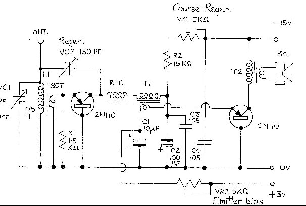 I did seriously consider giving up at this stage and taking up heavy drinking. What I did do was go on holiday for several days and come back to it with dogged determination. Additional R.F. bypass capacitors were added in case the audio stage thought it was an R.F. oscillator as well. Putting these in the wrong place such as across the output made matters worse. However, attempts to further tame the detector by placing a damping resistor across the aerial coil coupling winding to Tr1 and increasing the value of the collector resistor eventually produced results. The value of both was determined by experiment and is shown on the final circuit diagram. A variable resistor of 5K was included in series with the collector resistor, which was now 15K. This made the collector voltage adjustable since it was obvious it was an important parameter in keeping things stable. The final circuit (on the right) looks a bit different to Mr Bettridge's because it has had to evolve but I hope it is in the spirit of the original.
At long last, months after putting solder to iron, I was able to listen to the sound of a radio station coming from a speaker courtesy of two small devices of the type that had ushered in the transistor era in a circuit that was hopefully not too dissimilar to those available to the early enthusiasts.
HIGH FASHION
Mr Bettridge's miracle was housed in a Perspex case. In the early 50's this hinted at modernity and atomic age technology and had the added advantage that you could look inside and go, "look, no valves". It was therefore essential that even a partial replica should be in a similar case and use similar construction techniques. The problem was that the illustrations of the receiver in Wireless World appeared to show a variant of his more complex circuit. However by careful scrutiny it was possible to deduce basic dimensions from such facts as the use of a three and a half inch speaker. He also described the use of a construction technique using stiff wire buses anchored to short sections of wire sealed into the Perspex after heating with a soldering iron. So by using these facts and with a little knowledge of other components that would have been readily available at the time a radio could be put together similar to one a reader of Mr Bettridge's article might have produced.COMPONENTS
There was no component list or detailed layout in Wireless World so this was obviously meant for the more resourceful constructor, or the more foolhardy depending on your point of view. Modifications to take account of what was available at the time would have been normal. Guidance was given for some of the components, for others the specification is vague or non existent.The coupling transformers specified were hearing aid types by Multitone and were actually very small for their day. The important parameters were a high primary impedence and a step down ratio of about 5:1. I used an Eagle type P631M from Maplin ( prim. resistance 1K., impedence 20K. sec. Resistance 50 ohm. impedence 1K. ) for T1 and a miniature 9v mains transformer, same source, for T2. This has nearly 4Kohms primary resistance and works well. Attempts to use two of the Eagle transformers produced instability, probably because of coupling through identical inductances. So to make life simple, I didn't!
In the Wireless World article the tuning coil is a "Weyrad" type with tuning slug and a tap one fifth from the earthy end. Not having one of these I used a small wave wound medium wave local oscillator coil on a paxolin former of the type Pye employed in their fifties transistor radios. It has a main winding of 175 turns tapped and a coupling winding of 35 turns.
The reaction capacitor used by Bettridge was a form of preset but the detail of this was not clear from the photographs. Since I was going for limited tuning and more control of the wayward reaction I used two ceramic base variables with open vanes, of the type common at the time, one of 150pf for reaction and one of 50pf for tuning. Two 150pf's would have been better but these were what I had to hand. The solid dielectric "Dilecon" type would also have been suitable for the period but the smaller metal framed variables had yet to appear with the first commercial transistor radios.
Electrolytic capacitors were the physically biggest axials I could get. I had some new old stock types and with the plastic sheath removed they looked about right although still too small.
For R.F. bypass I used some good wax paper tubulars that I had saved although I was a bit worried they would have higher inductance and trigger the dreaded instability again because I had used disc ceramics in the test lash up. The tubulars will not be subjected to the same high voltage stress that they would in a valve radio and provided the wax is not degraded they shouldn't absorb too much moisture which at worst would increase their capacitance.
I tried to use one watt or half watt carbon composition resistors and fairly stiff uncovered interconnecting wire. The 2N110 holders were made from cut down integrated circuit sockets. For the holder leadouts I used salvaged laquered fabric wire. No coloured PVC connections in this 1954 replica!
FINAL CONSTRUCTION
Construction of the case was relatively uneventful using offcuts of 5mm thick Perspex. Pins for anchoring were made from short lengths of stiff wire inserted with pliers and a 30W iron. All drilling on the front face, the fixing in place of the supply bus wires and the soldering of most components was done before the side pieces were fixed in place to facilitate ease of construction. The side pieces were superglued on although in the original they were screwed on using thicker Perspex.Inevitably there are differences in the finished layout compared to the Wireless World radio since two variable capacitors now have to be accommodated. Bettridge's original layout had used a high value variable resistor as an attenuator in the aerial input. I wasn't using this method of signal control. Instead I was using a variable resistor in the collector of TR1 to give course reaction adjustment, so this replaced Mr Bettridge's attenuator at the lower left corner of the front panel.
SETTING UP AND RESULTS
The receiver has a couple of idiosyncrasies. It appears to need to warm up! After switch on I often find that sufficient reaction is difficult to obtain at any combination of settings or only occurs at minimum setting of C2. Immediate adjustment of the controls to provide a satisfactory signal will result in the receiver bursting into oscillation after a short time. In practice it is best to leave it for a minute or two after applying power and then adjust VR1 to just below oscillation point with C2 at mid travel before finding the optimum setting of C2 and resetting the tuning. I put this effect down to the base leakage current through the germanium crystal which heats up slightly increasing the leakage further until equilibrium is achieved. The temperature dependence is exacerbated by the auto bias technique used, optimum reaction always being affected by large ambient temperature change.A second effect concerns the stable tuning range of the receiver. In a sense this is common to most simple regenerative receivers but is more pronounced here with instability increasingly difficult to control as the tuning capacitor is closed. There may be an optimum ratio between the tuning capacitor and C2 so that for tuning in a station at the low end of the band it may be better to increase the coil inductance by means of its tuning slug.
While we are on the subject of regenerative receivers I am reminded of Captain P.P. Eckersley's warning of the 1920's on the subject of radiating howls, " Please don't do it!". I would like to assure you that no neighbouring radios were assailed during these adjustments and that the aerial was temporarily disconnected!
From a performance point of view this radio is not loud and it also suffers from a continuous background hiss, although even that is not loud. In a quiet room it is possible to follow programme content quite well, particularly on speech. Music is a bit more problematical because of distortion which is most obvious when the circuit is at its most unstable point just below oscillation. If detector reaction is backed off a little things improve but there is a trade off between output level and distortion. A bigger diameter speaker would give improved acoustic coupling with these meagre output levels.
Some readers will be familiar with the illustration of the 1951 experimental receiver by GEC which appears in the book "The Set Makers". Close inspection of this seems to indicate that it is a TRF receiver. RCA and some other American companies demonstrated experimental Point Contact superhet receivers prior to 1953 but it is not difficult to appreciate why equipment manufacturers did not see the Point Contact transistor as having a future in mass produced domestic radios. Telephone networks, tone oscillators and computer switching circuits provided a home for many of these early Point Contact transistors but a superhet receiver was altogether a different proposition requiring a local oscillator to work reliably over a wide frequency range and several I.F. amplifiers to provide stable gain without tricky setting up adjustments. A further consideration was that all these devices were literally hand assembled and the process didn't lend itself to mass production which was going to keep unit costs high.
SUMMARY
The Bettridge circuit proved not to work for me exactly as described using conventional regenerative feedback. This is not because Mr Bettridge was a charlatan, indeed the circuit probably arose from the GEC development lab, but is most likely due to the slightly different characteristics of the 2N110 compared to the GET1. Then again all these early devices differed so possibly some samples of the GET1 did in fact display the negative resistance effects noted. It is certainly obvious that other enthusiasts at that time were using this principle in their own circuits.I have carried out some further experiments using additional 2N110s and although these are not yet complete it is clear that for someone trying to replicate this circuit it would not be easy. It is however not impossible and is a challenge for anyone who is prepared to investigate these circuits while the devices are still available. Perhaps also this account will trigger memories for someone who recalls these early circuits or who actually built them or who remembers someone who did. It would be very satisfying to hear of their experiences either direct or through these pages and to further add to our knowledge of the early transistor experimenters.
I mentioned earlier other available construction articles and the following is a brief sample.
- Radio Constructor March 1956; "The Transistorette", a "portable" designed for use with a short throw out aerial! Essentially an amplified germanium diode detector feeding a speaker. Uses early junction transistors.
- Radio Constructor December 1956; "The Evesdropper", a personal TRF receiver using an early surplus RF junction transistor.
- Radio Constructor August 1957; A superhet using white and red spot transistors and the Pye intermediate frequency of 315 kcs.
POSTSCRIPT*
Two people deserve acknowledgement in connection with this article. Jack Ward who supplied the transistors and encouragement and Andrew Wylie who supplied additional information. I am also indebted to Andrew Wylie for some potentially important new historical facts that came to light after I started this article. I have decided to do justice to them here rather than clutter up the narrative of the introduction.The first Bell transistor operated in the lab just before Christmas 1947 but Bell decided not to publicly announce it until June 1948. The production of a point contact device in the U.K. by both BTH and GEC before the end of the same year is perhaps not so surprising since both were involved in wartime radar crystal detector work. These organizations had expertise in purifying germanium and could have replicated the results announced by Bell quite soon afterwards. What we don't know is whether they were carrying on any similar research themselves prior to this. There is an interesting photograph of a wedge shaped point contact device ascribed to BTH in 1948 in the book Crystal Rectifiers and Transistors.
However it now appears that two German physicists, Herbert F Matare and Heinrich Welker, working at Westinghouse research labs in Paris, independently and without knowledge of the Bell results, fabricated a working device very similar to Bardeen and Bratain's Transistor in about February of 1948. They called their Point Contact amplifier the Transitron and its significance was almost immediately celebrated in the French press although Westinghouse were slow to follow it up with a patent. Had they done so they could have pre empted Bell's June announcement for which Bardeen and Bratain shared the Nobel Prize. Perhaps in time we may come to regard Matare and Welker as co inventors along with the Bell team unless some further revelations come to light!
Andrew is very fortunate to have one of these rare Transitrons and the IEEE are excited enough to have commissioned a special article on its development. I would recommend those interested to visit Andrew Wylie's website where a fuller account complete with photographs can be obtained.
BIBLIOGRAPHY
- Crystal Rectifiers and Transistors; edited M.G. Say, published by Newnes 1954.
- Transistors and Crystal Diodes, What They Are And How To Use Them; author B.R. Bettridge, first published by Norman Price 1954. ( Published after the Wireless World article and obtained before this piece was finished at Andrew Wylie's recommendation).
- Handbook Of Semiconductor Electronics; edited Lloyd P. Hunter, published by Mc Graw Hill sec. Edition 1961.